To detect the corners of objects in an image, one can start by detecting edges then determining where two edges meet. There are however other methods, among which:
the Moravec detector [Moravec 1980],
the Harris detector [Harris & Stephens 1988].
Moravec detector
The principle of this detector is to observe if a sub-image, moved around one pixel in all directions, changes significantly. If this is the case, then the considered pixel is a corner.
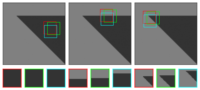
Figure 1:Principle of Moravec detector. From left to right : on a flat area, small shifts in the sub-image (in red) do not cause any change; on a contour, we observe changes in only one direction; around a corner there are significant changes in all directions.
Mathematically, the change is characterized in each pixel of the image by which represents the difference between the sub-images for a translation :
where:
and represent the translations in the four directions:
In Figure 1, only the two translations and are shown for simplicity
is a rectangular window around pixel ,
is the difference between the sub-image and the translated sub-image ,
In each pixel , the minimum of in the four directions is kept and denoted . Finally, the detected corners correspond to the local maxima of , that is, at pixels where the smallest value of is large.
It turns out that Moravec detector has several limitations. First, is a binary window and therefore the detector considers all pixels in the window with the same weight. When the noise in the image is high, it can lead to false corner detections. Second, only four directions are considered. Third, the detector remains very sensitive to edges because only the minimum of is considered. For these reasons, Harris has proposed a detector to overcome these limitations.
Harris detector
To avoid a noisy response, the rectangular window of the Moravec detector is replaced by a Gaussian window in the expression of .
To extend the Moravec detector to all directions (not only the initial four directions), a Taylor series expansion is performed on the shifted sub-image :
so :
This expression can be written in the following matrix form:
where
If a corner is present at pixel , then the derivatives of are very large, so has large coefficients, so the eigenvalues and of are also very large. Because the calculation of the eigenvalues can be cumbersome, it is attractive to use other quantities related to the eigenvalues. Harris propose to use the trace and determinant of the matrix . These values can be calculated easily:
Finally, Harris propose to calculate
with . The values of are low in a flat regions, negative on edges, and positive on corners. An example is given Figure 2.
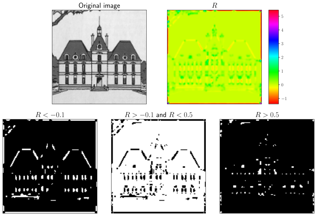
Figure 2:Harris detector. The binary images represent the negative (contours), weak (flat areas) and positive (corners) values of the coefficient .